| HOMEPAGE | BELL- RINGING UNITS | EXAMPLES of TOWERCLOCKS | mail
to |
|
T O W E R C L O C K S |
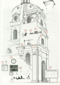 |
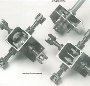
1+2 master and signalclock |
| 3 central drive mechanism | |
| 4+5 dial trains bevel gear | |
| 6 dial faces and hands | |
| 7 hammer train | |
| 8 bell ringing machine | |
| 9 motorised dial train | |
| 10+11 hymndisplay and showcase |
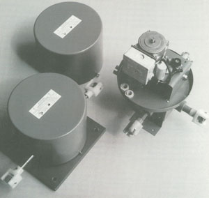 |
CENTRAL
DRIVE MECHANISM FOR TOWERCLOCKS
2-sided and 4-sided
drive with capacitor motor with thermal protection gears phosphor bronze worm wheel gears with adjustable ball bearing, precision functioning free from play with worm wheel drive housing weather-resistant aluminium power supply 230V / 50-60Hz / 150VA drive minute impuls 24V DC or 230V AC reset after power failure by cycle delay unit for master clock in common power circuit or extern ZSP-unit housing dimensions in cm see sketch |
 |
 |
 |
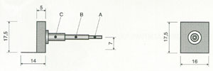
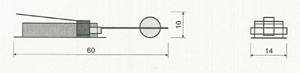
DIAL
TRAINS are precise and durable gears whitch convert the minute
rotation of the minute arbor to the hour tube. The environmental forces
working on the dial trains such as wind pressure and icing are
compensated by solid construction an proffessional installation
Dial face Ø max. 2,5m or 4,0m
Minute arbor A 14 mm
Ø
Hour tube B
25 mm
Ø
Drive tube C
35 mm Ø
BEVEL GEARS are installed in the transmission between the towerclock central drive and the dial trains |
 |
|
 |
DIAL
FACES and HANDS
The apearance of the dial faces and hands has been
developed in consultation with the Austrian Historic Building
Departement and the Diocesan Bilding Authorities.
Their polyester construction guarantees high resistance to wind and
stresses coused by weather. The dye penetration of the material itself
ensures that no colour change occurs even after years. This form
of production has been in continuous and successful use since 1968
ZBLR round for diameter from 0,7-3,0m ZBLQ square for side lenght of 0,7-3,0 m |
 |
 |
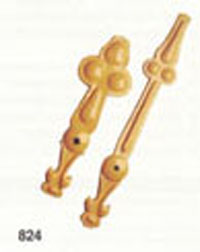 |
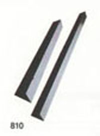
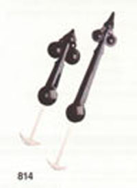
HANDS
Typ Z810 standard - form (
konish ) for dial face diam. from 0,7 to 7,0m
Typ Z814 standard - form ( tradition ) for
dial face diam. from 0,7 to 4,0m
Typ Z824 standard - form (
baroke ) for dial face diam. from 0,7 to 4,0m
also different special forms and materials
|
 |
 |
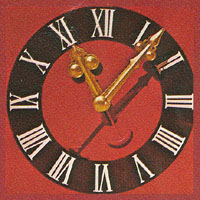 |
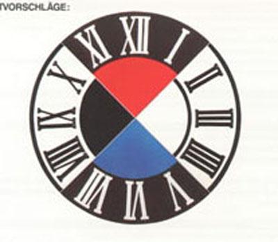
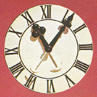
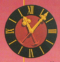
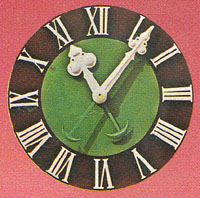
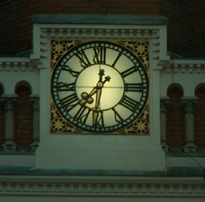
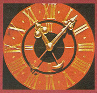
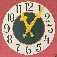
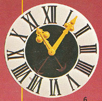
DIAL
FACES
in different types ( from left
to right )
Nr. 10; 11; 18; |
 |
 |
 |
Nr. 19; X; 23; |
 |
 |
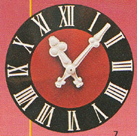 |
Nr. 25; 6; 7; |
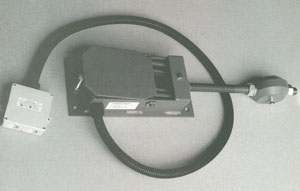 |
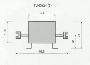
MAGNETIC
HAMMER TRAIN
electromechanical device which strikes the quaters and hours on a bell. Striking train impulse from the master clock. the striking force required can be set individually to suit the size of bell. The powerpack rectifies the voltage from 230V AC to 180V DC dimensions in cm see sketch |
 |
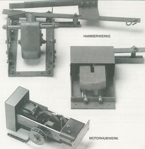 |
MOTORISED
LIFTING TRAINS electromechanical devices
whitch actuate the hammer trains for striking the quaters and hours via
chain and cable pull on a bell.
Lifting hammer trains for bells from 50 kg to more then 10
tons
HAMMER TRAINS Typ HWK for bells up to 700kg Typ HWM for bells up to 1.500kg Typ HWG for bells up to 10.000kg and more |
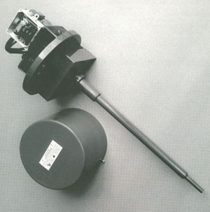 |
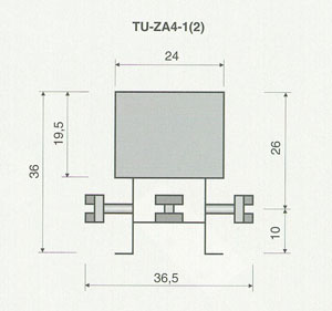
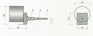
MOTORISED
DIAL TRAIN
for driving the hands directly. They are used in towers where install a
central drive mechanism for the towerclock is impossible or the tower
only has one dial face.
TECHNICAL PARAMETERS like central drive mechanism Dial face Ø max. 2,5m or 4,0m Minute arbor A 14 mm Ø Hour tube B 25 mm Ø Drive tube C 35 mm Ø housing dimensions in cm see sketch |
 |